This article is the first in a series, documenting my journey building a Tayloe Demodulator as an HF radio receiver. This article focuses on a Spice simulation of a Tayloe demodulator.
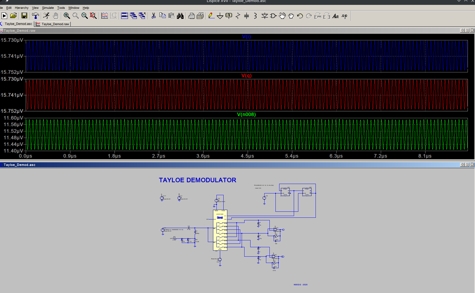
The schematic shown in Figure 1 was created with LTSpice, a well know Spice circuit simulator and schematic capture application. I recommend it.
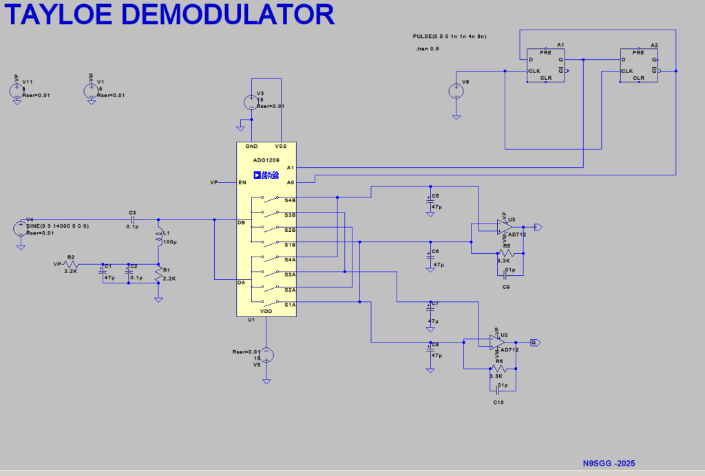
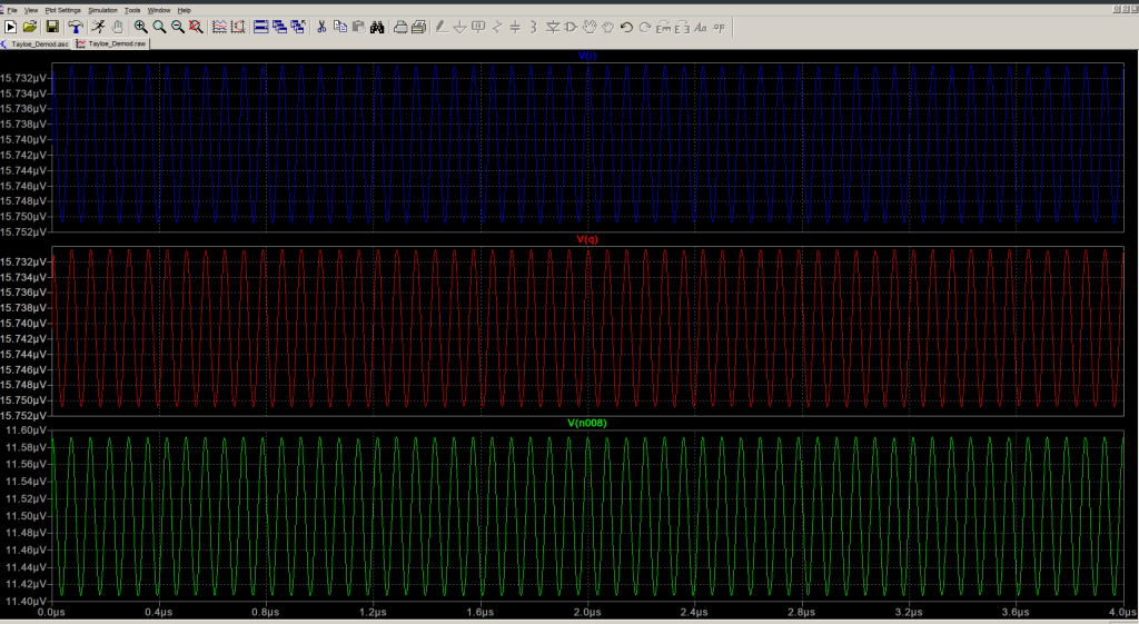
Simulation
So, now we have a circuit simulation at 14 MHz input signal.. The Spice netlist is shown below
* Z:\home\n9sgg\workspace\DirectConverion_Tayloe\Tayloe_Demod.asc
XU1 N012 N001 N002 VP N004 0 N009 N010 N006 N005 N008 N009 N010 N006 N005 N008 ADG1209
C1 N011 0 47µ V=50 Irms=1.49 Rser=0.044 Lser=0
C2 N011 0 0.1µ V=16 Irms=0 Rser=11 Lser=0
R1 N011 0 2.2K
L1 N008 N011 100µ Ipk=0.62 Rser=0.559 Rpar=94050 Cpar=2.707p mfg="Bourns, Inc." pn="SDE0604A-101K"
R2 N011 VP 2.2K
A1 N001 0 N003 0 0 0 N002 0 DFLOP Vhigh=5 td=10n
A2 N002 0 N003 0 0 N001 0 0 DFLOP Vhigh=5 td=10n
XU3 N005 N009 VP VM I AD712
V3 N004 0 15 Rser=0.01
C3 N008 N007 0.1p
V4 N007 0 SINE(0 3 14000000 0 0 0) Rser=0.01
V5 0 N012 15 Rser=0.01
V6 N003 0 PULSE(0 5 0 1n 1n 4n 8n)
C5 N005 0 47µ V=50 Irms=1.49 Rser=0.044 Lser=0
C6 N009 0 47µ V=50 Irms=1.49 Rser=0.044 Lser=0
C7 N006 0 47µ V=50 Irms=1.49 Rser=0.044 Lser=0
C8 N009 0 47µ V=50 Irms=1.49 Rser=0.044 Lser=0
R5 I N009 3.3K
C9 I N009 .01p
XU2 N006 N009 VP VM Q AD712
R6 Q N009 3.3K
C10 Q N009 .01p
V11 VP 0 5 Rser=0.01
V1 VM 0 -5 Rser=0.01
* TAYLOE DEMODULATOR
* N9SGG -2025
.tran 0.5
.lib ADG1209.sub
.lib ADI1.lib
.backanno
.end

The trick was finding out about the DFLOP parameters. Vhigh=5 and td=10n, so we get 5V out of the dflop and it has a time delay of 10n seconds.
Next is the PCB layout for the receiver. Using KiCad was a bit of a learning curve but well worth it IMHO.
Next in the series is the Tayloe Modulator article. Stay tuned for more!